oProcedure and protocol for Dry heat sterilizer (DHS) validation, DHS consists of accurately measuring the temp. at critical points within the sterilization chamber throughout the process. Dry heat process generally employs a temperature between 250°C and 400°C for varying time. The sterilizer is required to heat all parts of its load up to the specified temperature for a specified period long enough to achieve the desired sterility.
Dry Heat Sterilizer (DHS) Validation Protocol
Table of Content – Dry heat sterilizer (DHS) validation Protocol
| Sr. No. | Content | Page No. |
| 1. | Approval Signatures | |
| 2. | Objective | |
| 3. | Scope | |
| 4. | Reference Document | |
| 5. | Equipment Description | |
| 6. | Responsibility | |
| 7. | Qualification Test Method | |
| 8. | Re Qualification | |
| 9. | Documentation | |
| 10. | Conclusion | |
| 11. | Abbreviations | |
| 12. | Annexure |
1.0 Approval Signatures
Signing of this performance qualification protocol indicates the agreement with the performance qualification procedure of Dry Heat Sterilizer (DHS). Further if any changes in this procedure are required, protocol will be revised and duly approved.
| Prepared By | ||
| Name/ Designation | Signature | Date |
| Checked By | ||
| Name/ Designation | Signature | Date |
| Approved By | ||
| Name/ Designation | Signature | Date |
2.0 Objective:
-
- The purpose of this protocol is to provide the procedure for the performance qualification of the Dry Heat Sterilizer (DHS).
-
- To provide documented evidence that the equipment is capable to continuously maintaining the clean environment with the specified quality attributes thereby establishing its dependability.
-
- To prove the adequacy of the engineering design of the equipment and the effectiveness of the operating control and maintenance procedures.
3.0 Scope
-
- This qualification protocol covers all aspects of Performance Qualification for the Dry Heat Sterilizer (DHS) installed in the pharmaceutical plant / microbiological laboratory.
4.0 Reference Document
-
- Following documents are referred during preparation of the protocol
| Document Name | Document Number |
| Operational and Cleaning SOP of Dry Heat Sterilizer (DHS) | |
| Operation and Maintenance Manual | |
| Operation Qualification Protocol |
5.0 Equipment Description – Dry Heat Sterilizer (DHS)
-
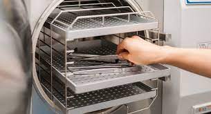
- The Dry Heat Sterilizer (DHS) is a unique sterilization system, as it can be efficiently used to perform Dry Heat Sterilization processes.
-
- As the name suggests the above process achieves sterilization with the help of Hot Air.
-
- The sterilization system has been designed to work at a maximum temperature up to 2750C. The moisture removal phase has been designed for removing moisture from the washed load. The heat up phase increases the temperature of the load from ambient temperature to the sterilization temperature.
-
- The sterilization phase consists of the balancing period, the sterilization hold time and safety period.
-
- The cooling phase cools the load to the desired temperature by rapid air change connection technique.
-
- The unloading phase continues to maintain over pressure in the chamber for containment barrier.
-
- Special airflow technique guarantees over pressure in the chamber throughout the cycle for 100% sterile integrity of the load.
-
- Sterilization chambers are designed and build to confirm with the most advanced technology and comply to international standards.
-
- The efficiency of the Dry Heat Process depends on the velocity and circulation pattern of air within the sterilization zone.
-
- Dynamically balanced S.S. impeller is provided for faster cooling.
-
- Improved impeller drive system with high temperature bearings and motor mounting arrangement for lower vibration and sound levels.
-
- Airflow pattern for better temperature uniformity between top – bottom and sides.
5.0 Responsibility
-
- Responsibilities of different department/ personnel involved in different activities related to the performance qualification of Dry Heat Sterilizer (DHS) are defined below:
-
- Quality Assurance (Validation)
-
- Preparation of PQ protocol
-
- Approval of PQ protocol.
-
- Execution of PQ study along with the co-ordination of other departments.
-
- Review of results and compilation of reports.
-
- Preparation and approval of PQ report
-
- Quality Control
-
- Checking of PQ protocol and report.
-
- Performing testing.
-
- Preparation of analysis report and submission to Quality Assurance.
-
- Engineering
-
- Preventive Maintenance of Dry Heat Sterilizer (DHS) as per schedule.
-
- Rectification of breakdown during qualification study.
6.0 Pre-Qualification Tests – Dry Heat Sterilizer (DHS)
-
- Pre-Requisites
-
- Prior to compiling the Performance Qualification report following things must be reviewed.
-
- Standard Operating Procedure Verification
-
- Measuring Instrument’s Calibration status Verification.
-
- Test Instrument’s Calibration status Verification.
-
- Standard Operating Procedure Verification
Objective
To verify that standards operating procedures required in the qualification of Dry Heat Sterilizer (DHS) are of current revision.
| Sr. No. | SOP Title |
| 1 | Operation and Cleaning of Dry Heat Sterilizer (DHS) |
| 2 | Operation and Calibration of Data Logger. |
| 3 | Preventive Maintenance of Dry Heat Sterilizer (DHS) |
- Measuring Instrument’s Calibration Status Verification.
Objective : To ensure the calibration status of all measuring instruments attached to the equipment, as given in table below, before qualification study.
Acceptance Criteria : All measuring instrument attached to the equipment should be in calibrated state.
| Sr. No. | Measuring Instruments |
| 1 | Pressure Gauge |
| 2 | Magnehelic Gauge |
| 3 | Differential Pressure Transmitter |
| 4 | Strip Chart Recorder |
| 5 | Temperature Transmitter |
| 6 | Temperature Controller |
| 7 | Temperature Sensor |
-
Test Instrument’s Calibration Status Verification.
Objective : To ensure calibration status of all test instruments to be used during PQ study, as given in table below, before qualification study.
Acceptance Criteria : All Test instruments to be used during PQ study should be in calibrated state.
| Sr. No. | Test Instruments |
| 1 | Aerosol Photometer |
| 2 | Anemometer |
| 3 | Particle Counter |
| 4 | Data Logger (Kay Validator) |
| 7 | Thermocouples (from 01 to 20 No.) |
7.0 Qualification Test Method – Dry Heat Sterilizer (DHS)
The following Tests shall be carried out to establish the Performance Qualification of Dry Heat Sterilizer (DHS):
-
- Integrity Testing of HEPA Filters
-
- Air Velocity Studies
-
- Non Viable Air Borne Particulate Count Studies
-
- Air Flow Pattern Studies
-
- Empty Chamber Heat Distribution Studies
-
- Loaded Chamber Head Distribution and Heat Penetration Studies
-
- Endotoxin Challenge Studies
-
Integrity Testing of HEPA Filters (By outside party) …… (Refer SOP for Integrity Test)
- Objective : To ensure the integrity of the HEPA Filters installed in the Dry Heat Sterilizer (DHS).
-
- Test Requirements :
-
- DOP Generator
-
- Calibrated Aerosol Photometer
-
- Compressed air/Nitrogen source
-
-
Test Procedure :
-
-
- Switch “ON” the Blowers of the Dry Heat Sterilizer (DHS). Switch “OFF” the heaters. Let the blowers run for 15 minutes for chamber equilibration.
-
- Direct the flow of aerosol from aerosol generator at the pre-filter of inlet air duct of Dry Heat Sterilizer (DHS) by giving adequate pressure using nitrogen or compressed air of pressure not less than 1.5 kg/cm2.
-
- Switch the Aerosol Photometer “ON” and allow stabilizing for few minutes.
-
- Adjust the aerosol generation to achieve a DOP challenge concentration of approximately 20-80 mg/liter of air.
-
- Adjust this challenge concentration at upstream of the HEPA filter and check for detection in photometer.
-
- Scan the HEPA Filter surfaces and periphery by passing the receptor probe 1 inch from the filter surface, in overlapping strokes for any leakage.
-
- Acceptance Criteria
-
- The DOP penetration/leak through HEPA filters should not be greater than 0.01% of the upstream DOP concentration.
-
- Results
-
- Record the observations in Annexure 1.
-
Air Velocity Measurement Studies
- Objective
-
- To demonstrate that the air system is balanced and capable of delivering sufficient air volumes to maintain a minimum cross-sectional velocity under the HEPA filters of at least 90 fpm (0.45 m/s ± 20%) measured 6 inches downstream of the HEPA filters of the Dry Heat Sterilizer (DHS).
-
- Test Requirements
-
- Calibrated Anemometer
-
- Test Procedure
-
- Switch “ON” the Blowers of the Dry Heat Sterilizer (DHS). Keep the Heaters “OFF”. Let the blowers run for 15 minutes for chamber stabilization.
-
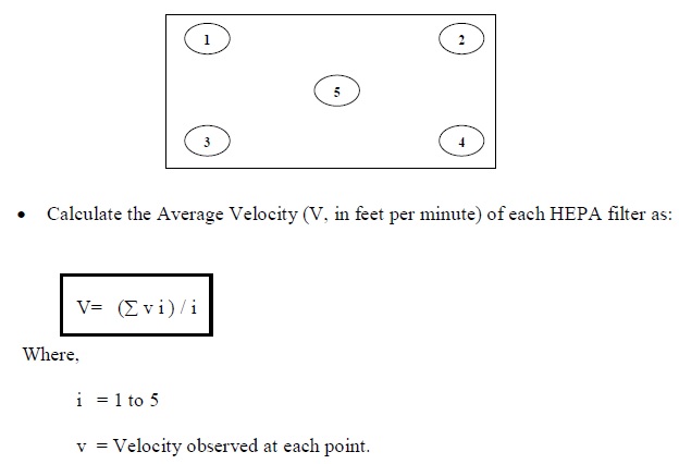
- Scan the area of the HEPA Filters installed in the chamber of Dry Heat Sterilizer (DHS) with Anemometer probe, 6 inches from the filter face.
-
- Note down the velocities at the center and corners of each HEPA filter, in Annexure 2.
Figure-1
-
- Acceptance Criteria
-
- The average measured clean air velocity should be 0.45 m/s ± 20% at 6 inches downstream from the filter face.
-
- Results
-
- Record the observations in Annexure – 2.
-
Differential Pressure Monitoring
-
- Objective
-
- The objective of this test is to show that the differential pressures across the filters & chamber are within designed values.
-
- Test Requirements
-
- Magnehelic Gauge
-
- Test Procedure
-
- Operate the Dry Heat Sterilizer (DHS) as per the SOP.
-
- Monitor the Differential Pressure during the following stage
-
- At initial During Heating Phase on the Chamber Magnehelic Gauge
-
- During the Depyrogenation Hold Phase on the Pressure Module Magnehelic Gauge.
-
- At the exhaust Phase on the Exhaust Module Magnehelic Gauge.
-
- Monitor the Differential Pressure during the all Cycles.
-
- Acceptance Criteria
| ∆P Across Chamber | The ∆P across the chamber should be between 10-30 mm of WC. |
| ∆P Across Pressure Module | The ∆P across the filter should be between 5-15 mm of WC. |
| ∆P across Exhaust Module | The ∆P across the filter should be between 5-15 mm of WC. |
-
- Results
-
- Record the observations and result in Annexure 3
-
Non Viable Particle monitoring
-
- Objective
-
- To establish the Class 100 conditions for Non-Viable Particulates inside the Dry Heat Sterilizer (DHS).
-
- Test Requirements
-
- Calibrated Air Borne Particle Counter.
-
- Test Procedure
-
- The test shall be carried out in three successive runs.
-
- Carry out the studies with Empty chamber in Dry Heat Sterilizer (DHS).
-
- Switch “ON” the Blowers of the Sterilizer. Keep the Heaters “OFF”. Let the blowers run for 15 minutes for chamber stabilization.
-
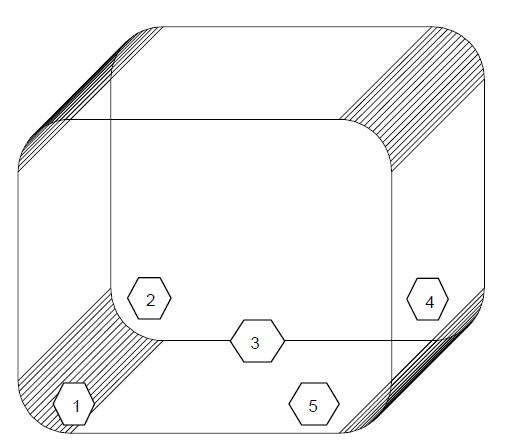
- Place the receptor probe at the locations given in the Figure 2.
-
- Operate the Particle Counter as per procedure. Programme the Particle Counter to take three readings of 1 minute from each location.
Figure 2
-
- Acceptance Criteria
-
- The particle count should meet the criteria defined in Table-1.
Table-1
| Particles/cubic feet | |
| ≥ 0.5 m | ≥ 5.0 m |
| NMT 100 | Nil |
-
- Results
-
- Record the observations in Form enclosed as Annexure 4.
-
-
Air Flow Pattern Studies
-
-
- Objective
-
- To verify the airflow in the chamber.
-
- Test Requirements
-
- Smoke Generator
-
- Test Procedure
-
- Carry out the studies in empty chamber conditions.
-
- Switch “ON” the blowers of the sterilizer. Let the blowers run for 15 minutes for chamber stabilization. Keep the heaters “OFF”.
-
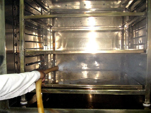
- Hold the smoke rod pointing in the direction of airflow in the center of HEPA filter in the chamber.
-
- Verify that the path of smoke stream generated is parallel to the airflow direction.
-
- Acceptance Criteria
-
- The Smoke Flow Pattern should move from HEPA filter to exhaust inside the chamber.
-
- Results
-
- Record the observations and attach the photographs in Annexure 5.
-
Empty Chamber Heat Distribution Studies
-
- Objective
-
- To perform the temperature mapping throughout the Dry Heat Sterilizer (DHS) in empty conditions and to locate the cold spot/coolest point if any, inside the chamber.
-
- Test Requirements
-
- Calibrated Data logger with calibrated probes (20 Nos.)
-
-
Test Procedure
-
-
- The test shall be carried out in three successive runs.
-
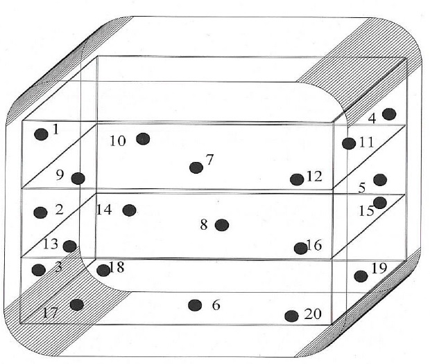
- Fix all 20 pre-calibrated probes through validation port as per the diagram enclosed as Figure-3.
Figure-3
-
- Out of total 20 probes, place 5 probes adjacent to the heat-controlling temperature RTD sensors, which will confirm that the operational controls are maintaining the desired heating specifications.
-
- Use Teflon tapes to secure probes in position. Ensure that the tips of probes where the wires are soldered do not touch any metallic surface.
-
- Attach the probes to the data logger.
-
- Operate the Dry Heat Sterilizer (DHS) as per procedure after setting the sterilization cycle parameters.
-
- Record the readings of all the temperature sensors with help of data logger and probes at intervals of every 1 minutes as required in form enclosed as Annexure 6.
-
- Locate the cold spot/coolest point in the chamber of the Dry Heat Sterilizer (DHS). Set the sterilization duration of equipment with respect to cold spot so that it remains at sterilization temperature for optimum sterilization time.
-
-
Acceptance Criteria
-
-
- In the chamber of Dry Heat Sterilizer (DHS) during the hold time should meet the following criteria:
-
- The measured temperatures in all the sensors should be within the range of 2500C – 2750
-
- Minimum exposure time should be NLT 60 minutes.
-
- The minimum FH value should be NLT 60 minutes.
-
- Results
-
- Record the observations and attach the print out of the data logger in Annexure 6.
-
Loaded Chamber Heat Penetration Studies
-
- Objective
-
- To perform the temperature mapping throughout the Dry Heat Sterilizer (DHS) in the loaded conditions.
-
- To locate the coolest point in the chamber of Dry Heat Sterilizer (DHS) for loads of all Loading Pattern
-
- Test Requirements
-
- Calibrated Data logger with calibrated probes (20 Nos.)
-
- Test Procedure
-
- Fix all 20 pre-calibrated probes through validation port as per the diagram enclosed as Figure-5.
-
- Out of the 20 pre-calibrated probes, place 5 probes adjacent to the heat controlling temperature RTD sensor, rest are placed in side the load which will confirm that the operational controls are maintaining the desired heating specifications.
-
- Use Teflon tapes to secure probes in position. Ensure that the tips of probes where the wires are soldered do not touch any metallic surface.
-
- Attach the probes to the data logger.
-
- Load the trays as per the loading pattern in to the Dry Heat Sterilizer (DHS) and operate the sterilizer as per procedure.
-
- Record the readings of all the temperature sensors with help of data logger at an interval of every 1 minutes.
-
- Down load the data from the data logger to the computer.
-
- Acceptance Criteria
-
- In the chamber of Dry Heat Sterilizer (DHS) during the hold time should meet the following criteria:
-
- The measured temperatures in all the sensors should be within the range of 2500C – 2750
-
- Minimum exposure time should be NLT 60 minutes.
-
- The minimum FH value should be NLT 60 minutes.
-
- The minimum endotoxin reduction should be NLT 3 log.
-
- Results
-
- Record the observations in Annexure 7.
-
Estimation of FH Value
-
- Objective
-
- Objective of this test is to ensure that,
-
- Minimum FH Value should not be less than 60 minutes,
-
- Procedure
-
- Record the temperatures at all Temperature mapping probes during the sterilization hold period.
-
- Calculate the FH Value at each Temperature mapping probe by using the equation given below.
-
- Record the FH Values (results) accordingly based on the type of study conducted.
-
- Compile the data generated during the qualification test for complete evaluation of the system.
-
- Prepare summary and conclusion of the performance qualification test, which will be finally approved by the Head – Quality control and Head – Quality Assurance.
-
- Basis of Calculations
-
- The temperature obtained during the empty chamber heat distribution/ loaded chamber heat penetration studies at different temperature sensing locations should be subjected for calculation of values at that particular location. The calculations are done by using the following formula.

-
- Where,
-
- dt = the time interval between successive temperature measurements (1 min.).
-
- T = the observed temperature at that particular time (As per the actual temperatures recorded)
-
- Z = the change in the heat resistance of Endotoxin as temperature is changed (46.4°C).
-
- Acceptance Criteria
-
- The Calculated minimum value (by equation a) should not be less than 60 minutes.
-
- Observations and Results
-
- Record the observations and results in the format enclosed as Annexure 8.
-
Endotoxin Challenge Studies
-
- Objective
-
- To demonstrate the degree of process lethality provided by the depyrogenation cycle, and to substantiate and supplement physical temperature measurements obtained from the probes.
-
- Test Requirements
-
- Spiked coli Endotoxin Vials.
-
- Endotoxin testing kit
-
- Test Procedure
-
- Spiking of vials:
-
- Reconstitute Endotoxin Indicators vial containing 100,000 Endotoxin units with 5 mL Lal Reagent Water [LRW] to give the concentration of 20,000 EU/ml.
-
- Vortex it for 10 to 15 minutes.
-
- Transfer 0.5 ml of the content (10,000 EU) in each vial to be spiked.
-
- Swirl the vial gently so that solution wets the entire inner surface area of the vial to be spiked.
-
- Air dry the spiked vial at room temperature under LAF.
-
-
Recovery of Endotoxin from spiked vials (Positive control):
-
-
- Add 4.0 ml LRW into the spiked containers (Assumed potency on the basis of 100% recovery = 2500 EU/ml).
-
- Sonicate the container for 10-15 minutes
-
- Dilute the reconstituted container as follows:
| Dil. No. | Dilution step | Concentration | Dilution ratio |
| 1 | 0.1 mL of 2500 EU/mL + 0.9 mL of LRW | 250 EU/mL | 1 :40 |
| 2 | 0.1 mL of 250 EU/mL + 0.9 mL of LRW | 25 EU/mL | 1 :400 |
| 3 | 0.1 mL of 25 EU/mL + 0.9 mL of LRW | 2.5 EU/mL | 1 :4000 |
| 4 | 0.1 mL of 2.5 EU/mL + 0.9 mL of LRW | 0.25 EU/mL | 1 :40000 |
| 5 | 0.5 mL of 0.25 EU/mL + 0.5 mL of LRW | 0.125 EU/mL | 1 :80000 |
| 6 | 0.5 mL of 0.125 EU/mL + 0.5 mL of LRW | 0.06 EU/mL | 1 :160000 |
-
- Perform the LAL Gel Clot test from dilution no. (4), (5) and (6).
-
- Record the results.
-
- Calculation
-
- Calculate by following formula:
-
- Recovery = Reciprocal of last dilution which was positive x lambda [l].
-
-
Recovery of Endotoxin from exposed spiked containers:
-
-
- Reconstitute the exposed container with 4.0 mL WFI. (Assumed potency on the basis of 100% recovery and considering 3 log reduction = 2.5 EU/ml).
-
- Sonicate the container for 10-15 minutes
-
- Dilute the reconstituted container as follows:
| Dil. No. | Dilution step | Concentration | Dilution ratio |
| 1 | 0.1 mL of 2.5 EU/mL + 0.9 mL of LRW | 0.25 EU/mL | 1 :40 |
| 2 | 0.5 mL of 0.25 EU/mL + 0.5 mL of LRW | 0.125 EU/mL | 1 :80 |
| 3 | 0.5 mL of 0.125 EU/mL + 0.5 mL of LRW | 0.06 EU/mL | 1 :160 |
-
- Perform the LAL Gel Clot test from dilution no. (1), (2) and (3).
-
- Calculation: Calculate the log reduction by following formula:
-
- Log reduction in endotoxin = log of recovered endotoxin from spiked container – log of recovered endotoxin from exposed containers.
-
- Acceptance Criteria
-
- A minimum log reduction of 3 should be achieved.
-
- Results
-
- Record the observations in the form attached as Annexure 9.
-
Re qualification of Dry Heat Sterilizer (DHS)
-
- Performance Qualification of Dry Heat Sterilizer (DHS) every year on all the tests mentioned above in this protocol.
-
- The qualification should also be performed additionally in case of following
-
- Any major modification in equipment after the last performance qualification. This must be properly documented through a change control system.
-
- Adjustments made in the instruments, to correct the non-compliance of operational parameters with respect to specifications.
-
Documentation – Qualification of Dry Heat Sterilizer (DHS)
-
- Results and reports shall be compiled in a binder. Binder shall contain the following sequentially
-
- Report
-
- Validation Protocol
-
- Test Reports
-
- The report shall be in narrative form, which describes the work as well as conclusion/certification regarding acceptability. Summary Report shall contain the following
-
- Post Approval
-
- Objective
-
- Brief validation methodology
-
- Acceptance criteria
-
- Evaluation of results
-
- Deviation, failure investigation reports and corrective actions (if any)
-
- Conclusion
-
Conclusion
-
- Based on the review of results a conclusion shall be drawn and documented in the summary report. Conclusion shall be a clear statement of compliance or noncompliance of the water system with the acceptance criteria of the performance qualification protocol.
| Abbreviations | Full Form |
| PQ | Performance Qualification |
| OQ | Operation Qualification |
| IQ | Installation Qualification |
| µ | Micron |
| °C | Degree Centigrade |
| WC | Water Column |
Annexure 1 – HEPA Filter Integrity Test Datasheet.
Equipment Details:
| Equipment | Area Location | ||
| Equipment ID | Area Classification | ||
| Room Id | |||
Test Instrument details:
| Instrument Name | Calibration Date | ||
| Make | Calibration Due Date | ||
| Instrument ID | Calibration Certificate Attached |
Observations:
| Sr. No. | HEPA ID/Serial No. | Observation (% Penetration) | (% Retention) |
| Acceptance Criteria | The DOP penetration/leak through HEPA filters should not be greater than 0.01% of the upstream DOP concentration. |
Conclusion:
Annexure 2 – Air velocity Measuring Datasheet.
Equipment Details:
| Equipment | Area Location | ||
| Equipment ID | Area Classification | ||
| Room ID | |||
Test Instrument details:
| Instrument Name | Calibration Date | ||
| Make | Calibration Due Date | ||
| Instrument ID | Calibration Certificate Attached |
Observations and Results:
| HEPA ID/Serial No. | Air Velocity in FPM | Average Air Velocity in FPM | Recorded By | ||||
| Location | |||||||
| 1 | 2 | 3 | 4 | 5 | |||
| 1 | |||||||
| Acceptance Criteria | Average measured clean air velocity should be 90 FPM ± 20% (0.45 m/s ± 20%). |
Conclusion:
Annexure 3 – Differential Pressure Monitoring Data Sheet.
Equipment Details:
| Equipment | Area Location | ||
| Equipment ID | Area Classification* | ||
| Room ID | |||
Test Instrument details:
| Instrument Name | Calibration Date | ||
| Make | Calibration Due Date | ||
| Instrument ID | Calibration Certificate Attached |
Observations and Results:
| Sr. No. | Date | Cycle Description | Cycle No. | DP Across Chamber1 | Across Pressure Module2 | Across Exhaust Module3 |
______________________________________________________
1 At Initial Heating Phase of Depyrogenetation Cycle
2 During Depyrogenation Cycle.
3 At end of Depyrogenation Cycle.
Acceptance Criteria:
| DP Across Chamber | The DP across the chamber should be between 10 – 30 mm of water. |
| DP Across Pressure Module | The DP across the filter should be between 05 – 15 mm of water. |
| DP Across Exhaust Module | The DP across the filter should be between 05 – 15 mm of water. |
Remarks:
Annexure 4 – Non Viable Particle Count Monitoring Data Sheet.
Equipment Details:
| Equipment | Area Location | ||
| Equipment ID | Area Classification* | ||
| Room ID | |||
Test Instrument details:
| Instrument Name | Calibration Date | ||
| Make | Calibration Due Date | ||
| Instrument ID | Calibration Certificate Attached |
Observations and Results:
| Particle Counter Used | |||||||||
| Calibration Status (tick mark) | Calibrated / Not Calibrated | ||||||||
| Equip. Name | Dry Heat Sterilizer | ||||||||
| Equip. ID. | QCM/002 | ||||||||
| Date | Location number | Sample #1 | Sample #2 | Sample #3 | Average | ||||
| 0.5µ | 5.0µ | 0.5µ | 5.0µ | 0.5µ | 5.0µ | 0.5µ | 5.0µ | ||
| Mean of location average | |||||||||
| Standard deviation of location average | |||||||||
| 95% UCL | |||||||||
Acceptance Criteria:
| ³ 0.5 m particle/ft3 | ³ 5.0 m particle/ft3 |
| NMT 100 | Nil |
Conclusion:
Annexure 5 – Air Flow Pattern Datasheet.
| Acceptance criteria | The flow should be from supply towards exhaust. |
Annexure 6 – Empty Chamber Heat Distribution Study Datasheet.
-
Depyrogenation cycle parameters
| Load | Load Configuration | ||
| Trial # | Trial date | ||
| Cycle # on the control Panel | |||
| S. No. | Parameter | Set Values in Cycle # … |
| 1. | Moisture Removal Temp. | |
| 2. | Moisture Removal Time | |
| 3. | Ster. hold temperature | |
| 4. | Ster. hold time | |
| 5. | Overshoot temperature | |
| 6. | Ster. count stop temp. | |
| 7. | Ster. Count reset temp. |
Remark
Cycle # …………………………………. is selected for Empty chamber Heat distribution studies of the Depyrogenation on the Dry Heat Sterilizer control panel with above set points for automatic operation of the cycle.
-
Loading pattern, Location of Temperature Mapping Probes
Load –
Date of Trial – ________ Trial # – _____
Location of Temperature Mapping Probes.
Remark – 20 No. of probes for temperature mapping were used. placed through out the chamber as per the schematic diagram.
| Details of additional Probe location | ||
| Probe Number | Location | Justification |
| 1. | ||
| 2. | ||
| 3. | ||
| 4. | ||
| 5. | ||
| 6. | ||
| 7. | ||
| 8. | ||
| 9. | ||
| 10. | ||
| 11. | ||
| 12. | ||
| 13. | ||
| 14. | ||
| 15. | ||
| 16. | ||
| 17. | ||
| 18. | ||
| 19. | ||
| 20. | ||
- Depyrogenation Cycle Thermograph with Dry Heat Sterilizer Print out.
Attach time, temperature profile from chart recorder and PLC printout.
- Temperature Profile – Empty Chamber Heat Distribution Study
Attach time, temperature profile from datalogger printout.
-
FH Calculation for the Sterilization Cycle
FH Calculation on the basis of Mathematical Calculation
Basis of Calculation
The actual observations obtained during the Heat distribution studies at different temperature sensing locations were compiled in the table and the observed temperatures were subjected for calculation of FH values at that particular location. The calculations are done by using the following formula and the lethality factor computed (during the sterilization period) are given in the following table.
Formula – Refer to protocol
Where,
dt = The time interval between successive temperature measurements (1 min.).
T = The observed temperature at that particular time (As per the actual temperatures recorded in the datalogger).
Z = The change in the heat resistance as temperature is changed (46.4°C).
Attach FH profile from datalogger printout
Observation
| Sensor number | Sterilization temp. Achieved at | Sterilization Completed at | Total Exposure time | Maximum Temperature during sterilization | Minimum Temperature during sterilization | FHValue | Remarks |
| 1 | |||||||
| 2 | |||||||
| 3 | |||||||
| 4 | |||||||
| 5 | |||||||
| 6 | |||||||
| 7 | |||||||
| 8 | |||||||
| 9 | |||||||
| 10 | |||||||
| 11 | |||||||
| 12 | |||||||
| 13 | |||||||
| 14 | |||||||
| 15 | |||||||
| 16 | |||||||
| 17 | |||||||
| 18 | |||||||
| 19 | |||||||
| 20 |
| Probe No. of Minimum FH Valve | Location of Probe having Minimum FH Valve | Minimum FH Valve |
Summary:
| Parameter | Acceptance Criteria | Observations | Remarks |
| Minimum temperature | NLT250 0C | ||
| Maximum temperature of cold spot | NMT 275 0C | ||
| Minimum Exposure Time | NLT 60 min | ||
| Minimum FH value | NLT 60 min. | ||
| Cold Spot Location | — |
Conclusion:
Annexure 7 – Loaded Chamber Heat Penetration Study Datasheet.
Refer to Protocol
Annexure 8 – Summary Report.
Refer to Protocol


